
Made in America
Get Connected With



Vacuum Welding is a controlled joining process performed inside a sealed chamber. Air and moisture are removed before the materials meet. This creates a cleaner working environment. It also reduces oxidation during heating.
The process usually combines heat, pressure, or a focused energy beam. Electron beam welding is a familiar example. Its narrow beam can melt metal precisely, even around delicate components. In other systems, heated surfaces contact under pressure and form a solid-state bond. The chamber may resemble a large steel vessel, with pumps humming while gauges track falling pressure.
“Clean surfaces and stable energy make the joint trustworthy,” explains Dr. Elena Marquez, a vacuum-welding process engineer. Her observation captures the central principle. Contamination can weaken the joint. Poor pressure control can distort the result. Unchecked heat may create residual stress.
A simple definition can mislead.
Vacuum Welding is not automatically perfect. Operators must select compatible materials, chamber pressure, temperature, and cooling rates. They also inspect weld depth, porosity, alignment, and surface condition. Aerospace parts, medical instruments, research hardware, and high-performance electronics may benefit from this precision. However, equipment costs remain high, and large components can create practical challenges.
This guide examines what Vacuum Welding means, how the equipment works, and why process control matters. It also considers common limitations. Real production rarely follows a flawless diagram. Small leaks, trapped gases, or inaccurate settings can change the outcome. Understanding those imperfections helps engineers make safer and more reliable decisions.
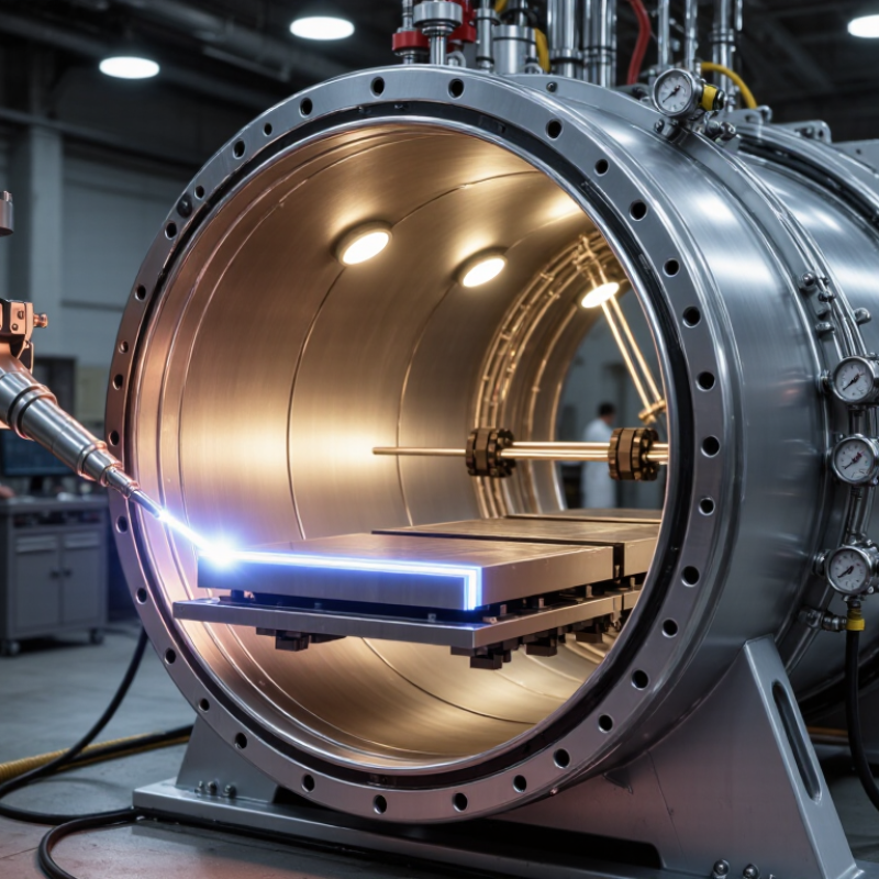
Vacuum welding joins materials inside a controlled chamber with very little air. The process may use heat and pressure, or a compatible filler metal. Diffusion bonding usually joins clean surfaces without melting them. Vacuum brazing uses molten filler metal to flow into narrow gaps.
Why use it? The vacuum removes oxygen, moisture, and surface contamination. This greatly reduces oxidation during heating. The result can be a clean joint with limited distortion and strong metallurgical contact. This matters when parts must keep precise dimensions. It also helps protect reactive materials, including titanium and certain high-temperature alloys.
Manufacturers use vacuum welding for heat exchangers, medical components, aerospace structures, and semiconductor equipment. Complex assemblies can often be joined without exposing them to open flames or atmospheric contamination. Controlled temperature cycles also improve repeatability between production batches.
It is not magic.
The surfaces must fit closely and remain clean. Poor preparation can create weak areas, trapped gas, or incomplete bonding. The equipment also requires substantial investment, careful temperature control, and qualified inspection. A vacuum chamber may reduce oxidation, but it cannot correct unsuitable materials or poor joint design. In practice, engineers should test the joint under expected heat, pressure, vibration, and corrosion conditions. I would not treat a shiny weld as proof of reliability; internal defects may remain invisible without appropriate testing.
Vacuum welding joins materials inside a low-pressure chamber. Removing most of the air reduces oxidation and contamination, allowing processes such as electron-beam welding, vacuum brazing, and diffusion bonding to produce clean, high-quality joints.
The chart shows representative vacuum levels commonly used in vacuum joining. A higher value means lower pressure and therefore a stronger vacuum. Actual settings vary with material, joint design, chamber size, and equipment.
Vacuum welding joins metals inside a controlled low-pressure chamber. The process removes air, moisture, and surface contaminants before bonding begins. Two common methods are electron-beam welding and diffusion bonding. Electron beams melt a narrow area. Diffusion bonding uses heat and pressure without creating a large molten pool.
A strong joint starts with clean, closely fitted surfaces. In diffusion bonding, atoms move across the contact line when heat and pressure activate the interface. The boundary gradually loses its identity. The interface vanishes. ASM Handbook Volume 6A identifies bonding temperatures commonly ranging from about 0.5 to 0.8 of the metal’s absolute melting temperature. Pressure, surface roughness, holding time, and alloy structure still control the final result.
Vacuum quality matters. Industrial procedures often work near 10⁻⁴ to 10⁻⁶ mbar, depending on the alloy and equipment. Lower pressure reduces oxidation, especially for titanium and reactive superalloys. NASA-STD-5006B emphasizes qualified procedures, inspection, and representative test coupons for critical welded hardware. That approach is practical because a visually perfect seam can still contain weak diffusion zones or hidden porosity. A polished surface is not automatically clean. Poor fit-up can also leave unbonded pockets. Engineers therefore measure hardness, tensile strength, and fracture location instead of trusting appearance alone. The process is powerful, but not effortless. Small preparation errors can weaken an otherwise precise joint.
Vacuum welding is a solid-state joining method performed inside a controlled vacuum chamber. Unlike ordinary fusion welding, it often joins materials without melting them. The process limits oxidation, trapped gas, and surface contamination. It is useful for high-temperature alloys, precision components, and delicate assemblies.
Technicians begin by cleaning both joining surfaces. Even a fingerprint can weaken the final bond. Parts are then aligned in a rigid fixture, because movement may create gaps. The chamber is sealed, and pumps remove air until the required vacuum level is reached. Heat gradually raises the components to a controlled temperature. Pressure is applied through the fixture, encouraging atoms to diffuse across the contact surfaces. The parts remain heated and compressed for a measured holding period. Cooling follows under controlled conditions, often inside the chamber. Sudden cooling can cause distortion or internal stress. The process sounds simple, but real parts rarely behave perfectly. Surface roughness, uneven pressure, and tiny particles can change the result.
Vacuum welding joins metal parts inside a controlled, low-pressure chamber. Electron beam welding is a common method. An electron gun accelerates electrons toward the joint. Their kinetic energy becomes intense, localized heat. The metal melts, flows together, and solidifies as the beam moves. No open flame is required. This reduces oxidation and helps protect reactive materials during joining.
Material selection remains critical. Stainless steel, titanium, nickel alloys, copper, and many refractory metals can respond well. However, thickness, thermal conductivity, and surface condition affect the weld. Dissimilar metals may require special process development. Remove oil, moisture, paint, and oxide layers before loading the chamber. Small contaminants can create porosity or unstable penetration. Cleanliness is practical, not cosmetic.
The equipment usually includes a vacuum chamber, pumps, an electron gun, motion controls, and monitoring instruments. Pressure must reach a suitable level before welding begins. The operator also controls beam power, focus, travel speed, and joint alignment. Tight tolerances matter because the beam is narrow. In practice, the process is less forgiving than diagrams suggest. A clean chamber is not enough. Fixtures can release trapped gas, and uneven heating can distort thin parts. A perfect-looking bead may still hide incomplete fusion. Test coupons, cross-sections, and documented settings provide stronger evidence than appearance alone. Conditions should be verified for each material combination.
What Is Vacuum Welding and How Does It Work?
Vacuum welding joins metals inside a low-pressure chamber. Electron beams, diffusion, or vacuum brazing can create the joint. Oxygen and moisture are greatly reduced, so oxidation stays low. NASA technical guidance commonly places electron-beam welding near 10⁻⁴ to 10⁻⁶ torr. That environment supports clean seams and narrow heat-affected zones.
Applications, Benefits, and Limitations of Vacuum Welding
This process suits aerospace structures, medical components, heat exchangers, sensors, and battery housings. It also handles reactive metals, including titanium and selected nickel alloys. The IEA’s Energy Technology Perspectives 2023 reports that industry uses about 37% of global final energy. Vacuum welding can reduce rework and filler-metal use, but it does not automatically reduce total energy consumption. Chamber pumps, heating systems, and long setup times add hidden costs. Large assemblies may not fit. Outgassing can also contaminate the chamber and weaken consistency. A perfect-looking seam still needs testing.
Tips: Control surface cleaning, fixture alignment, and chamber pressure. Record leak-rate checks before production. ISO 15614-1 supports documented welding procedure qualification. Use tensile, metallographic, or non-destructive testing when the joint carries critical loads. A practical mistake is trusting one successful sample too much. Production variation often appears later.
| Dimension | Description | Typical Data or Conditions | Primary Benefit | Main Limitation |
|---|---|---|---|---|
| Definition | Vacuum welding is a group of joining processes performed in a controlled low-pressure environment. Depending on the method, the joint is formed by solid-state bonding, localized melting, or filler-metal brazing. | Commonly includes vacuum diffusion bonding, vacuum brazing, and selected vacuum fusion-welding processes. | Reduces oxidation, contamination, and unwanted chemical reactions at the joint. | Requires specialized vacuum equipment and carefully prepared surfaces. |
| How the Process Works | Parts are cleaned, positioned, and placed inside a sealed chamber. Air and moisture are removed, heat and sometimes pressure are applied, and the assembly is cooled under controlled conditions. | Typical cycle stages: loading, evacuation, heating, joining, controlled cooling, and pressure release. | Provides repeatable thermal and atmospheric control. | Cycle times can be longer than open-atmosphere joining methods. |
| Vacuum Level | The chamber pressure is reduced sufficiently to limit oxygen, nitrogen, water vapor, and other contaminants around the joint. | Many industrial systems operate approximately between 10-2 and 10-5 mbar, depending on the process and material. | Helps prevent oxide formation and gas entrapment. | Leaks, outgassing, and chamber contamination can reduce joint quality. |
| Joining Mechanisms | Bonding may occur through atomic diffusion under heat and pressure, melting of the base material, or melting and flow of a compatible filler metal. | Diffusion bonding generally uses pressure below the material yield strength; brazing uses a filler metal with a lower melting range than the base materials. | Supports both solid-state and liquid-assisted joining designs. | Process parameters must be matched to material chemistry and joint design. |
| Typical Temperature Range | The required temperature depends on whether the process is diffusion bonding, brazing, or fusion welding. | Approximately 500–1,200 °C for many industrial applications; some refractory-material processes require higher temperatures. | Allows controlled joining of heat-resistant and reactive materials. | Thermal distortion, grain growth, or property changes may occur if the cycle is excessive. |
| Compatible Materials | Common materials include stainless steels, nickel-based alloys, titanium alloys, aluminum alloys, copper alloys, ceramics, and selected dissimilar-material combinations. | Compatibility depends on melting points, thermal expansion, surface chemistry, and filler-metal selection. | Can join materials that are difficult to weld in open air. | Some combinations require an intermediate layer or specialized joint design. |
| Joint Cleanliness | Surfaces must be free from oil, oxides, particles, moisture, and other contaminants before entering the chamber. | Cleaning may include solvent cleaning, alkaline cleaning, mechanical preparation, or controlled chemical treatment. | Improves wetting, diffusion, and joint consistency. | Poor preparation can cause voids, weak bonding, or incomplete filler flow. |
| Joint Quality | Controlled heating and atmosphere can produce clean joints with low spatter and limited surface oxidation. | Quality is evaluated using visual inspection, dimensional checks, leak testing, metallography, radiography, ultrasonic testing, or tensile testing. | Suitable for high-integrity and leak-tight assemblies. | Internal defects may not be visible without nondestructive testing. |
| Typical Applications | Used for heat exchangers, sealed tubes, high-temperature components, medical and laboratory assemblies, cutting tools, electronic packages, and complex multi-layer structures. | Especially useful where cleanliness, leak tightness, or resistance to high temperature is important. | Enables reliable joining of intricate parts and enclosed passages. | Large or unusually shaped components may exceed chamber size or heating capacity. |
| Dimensional Control | Uniform heating and controlled cooling can reduce uneven thermal gradients compared with many localized welding methods. | Actual distortion depends on part geometry, fixture design, heating rate, temperature, and cooling rate. | Often produces clean, visually uniform assemblies with limited post-processing. | Thermal expansion mismatch can still create warping or residual stress. |
| Environmental Benefits | The process does not require a continuously exposed shielding-gas stream around the joint, and it can reduce spatter, fumes, and surface-cleaning requirements. | Environmental performance depends on electricity use, pump operation, cleaning chemicals, and production volume. | Cleaner working conditions and less post-weld contamination. | Vacuum pumps, heating systems, and long cycles can increase energy consumption. |
| Equipment Requirements | A typical system includes a vacuum chamber, pumps, heating elements, temperature sensors, pressure gauges, fixtures, controls, and safety interlocks. | Some systems also require a force-loading mechanism, filler-metal fixtures, inert-gas backfilling, or programmable cooling. | Enables highly repeatable process control. | High initial investment and regular maintenance are required. |
| Production Suitability | Most suitable for batch production, specialized components, and high-value parts where joint performance justifies the process cost. | Throughput is influenced by chamber volume, load arrangement, pump-down time, heating rate, and cooling time. | Multiple parts can often be processed in one cycle. | Less economical for very large, simple, or low-cost assemblies. |
| Key Advantages | Low oxidation, clean surfaces, low spatter, good repeatability, strong leak-tight joints, and suitability for complex or dissimilar-material assemblies. | Performance depends on correct material selection, surface preparation, fixture design, and thermal-cycle control. | Improves joint integrity and reduces finishing operations. | Advantages may not justify the cost for ordinary fabrication work. |
| Key Limitations | Limitations include equipment cost, chamber-size restrictions, long thermal cycles, sensitivity to contamination, and the need for skilled process development. | A failed vacuum seal or incorrect heating profile can compromise an entire batch. | Known limitations can be managed through qualification and monitoring. | Not a universal replacement for arc, resistance, laser, or other conventional joining methods. |
Note: Values shown are representative industrial ranges. Actual parameters must be established through material data, joint design, equipment capability, and process qualification.