
Made in America
Get Connected With



An extruder can appear simple from the outside: material enters, heat and pressure build, and a shaped product emerges. Inside, however, each component affects output, consistency, and maintenance. Extruder Machine Parts such as the screw, barrel, feed throat, gearbox, heaters, screen changer, and die work as a connected system. A worn screw flight or poorly controlled barrel temperature can change melt quality, even when the rest of the line seems sound.
The scale of plastics processing makes these details worth understanding. PlasticsEurope’s Plastics – the Fast Facts 2024 report estimates global plastics production at 413.8 million tonnes in 2023. That figure describes production, not extruder sales, but it shows the enormous volume of material that processing equipment must handle. For buyers and operators, part selection should reflect resin type, throughput, operating temperature, and cleaning requirements—not just the machine’s purchase price. Small details matter.
This guide examines the parts that most directly shape extrusion performance, explains what each one does, and identifies practical signs of wear. It also considers how screw design, barrel condition, and die geometry interact during a production run. No single component is “top” for every application; a PVC profile line and a flexible-film line have different priorities. That distinction is easy to miss. Specific maintenance intervals and replacement choices should always be checked against the machine manufacturer’s documentation and the material supplier’s processing guidance.
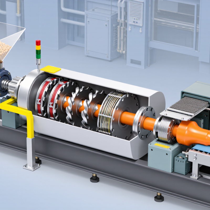
An extruder turns solid feed into a continuous stream of shaped material. Its core parts work together: the hopper feeds material into a heated barrel, while a motor and gearbox rotate the screw inside it. The screw’s flights move material forward and gradually compress it. The path is simple.
Heat comes from barrel heaters and friction created as material moves along the screw. The screw also helps mix the melt, though results depend on its geometry and the material being processed. Near the barrel outlet, a screen pack can catch contaminants and help stabilize flow. The die then shapes the pressurized melt into a profile, sheet, or strand. Not always. Temperature sensors and pressure readings help operators spot changes before they become visible in the product.
In practice, stable output depends on more than setting a heater temperature. Operators monitor melt pressure, motor load, and the appearance of the product. A rough surface or uneven strand may point to inconsistent feeding, worn screw components, or temperature variation. These clues are useful, but they do not identify a fault on their own. I would treat quick adjustments cautiously; changing several settings at once can hide the real cause. Regular inspection of the screw, barrel, heaters, and die helps maintain dependable operation.
What Are the Top Extruder Machine Parts?
Feeding Systems: Hopper, Throat, and Feed Mechanism
An extruder’s feeding system controls how consistently material reaches the screw. The hopper stores pellets and guides them downward; the throat connects it to the barrel. Poor flow can cause surging, uneven output, or empty stretches in the screw. The OECD’s Global Plastics Outlook (2022) reports that global plastics production reached 460 million tonnes in 2019. At that scale, repeatable feeding is more than a housekeeping detail.
The hopper should stay clean and dry, with walls that discourage material from bridging. A narrow throat can restrict flow, while excess heat near the opening may soften pellets too early. The feed mechanism, often a rotating screw, draws material into the barrel. Its performance depends on pellet shape, bulk density, and feed rate. Powders and regrind may behave differently from uniform pellets. A gravimetric feeder can help maintain a target rate by measuring material flow, but settings still need verification. One detail is easy to overlook: stable feed does not guarantee stable output.
Tips: Check hopper level and throat temperature during startup. Watch for bridging, dust buildup, and irregular screw loading. Record feed-rate changes; a small adjustment can have a noticeable effect.
| Component | Main Function | Key Design Considerations | Operating Checks |
|---|---|---|---|
| Hopper | Stores and directs pellets, granules, or other feedstock toward the extruder’s feed opening. | Capacity, outlet geometry, and wall finish should suit the material’s flow behavior. A hopper may include a lid, level sensor, or material-drying equipment when the process requires it. | Check for consistent material flow, contamination, bridging, and accumulation on the walls. Confirm that moisture-sensitive materials are handled according to their drying requirements. |
| Hopper Outlet | Channels material from the storage area into the throat or feed zone. | The opening must provide an appropriate flow path for the feedstock. Outlet size and shape should be selected with particle size, bulk density, and tendency to bridge in mind. | Look for blockages, uneven discharge, or material leakage. Keep the outlet and any screens or magnets clean where these are part of the setup. |
| Feed Throat | Connects the hopper outlet to the extruder barrel and guides material into the screw’s feed section. | Its opening must align with the screw and barrel feed port. Some designs use cooling around the throat to limit premature softening of thermoplastic feedstock. | Check for restricted flow, unwanted heating, and buildup. If throat cooling is installed, verify that coolant flow and temperature are within the equipment’s specified operating range. |
| Feed Screw | Rotates inside the barrel to convey incoming material forward; its feed section also helps capture and compact the material. | Screw diameter, channel depth, pitch, and rotation speed affect conveying and output. Screw geometry should be matched to the material and process requirements. | Monitor screw speed, motor load, and output stability. Investigate unusual wear, surging, or changes in throughput. |
| Feed Drive and Speed Control | Turns the screw and controls its rotational speed, influencing material conveying rate and production output. | The drive must be suitable for the required torque and operating conditions. Speed settings should be coordinated with downstream equipment and the rest of the extrusion process. | Check for abnormal noise, vibration, overheating, or fluctuating speed. Follow the machine manufacturer’s maintenance and safety procedures. |
| Metering Feeder (when fitted) | Supplies a controlled amount of material to the extruder. Volumetric feeders regulate volume; gravimetric feeders use weight measurements to regulate mass flow. | Feeder type and capacity should match the material’s flow characteristics and the required feed rate. Gravimetric systems require suitable calibration and stable weighing conditions. | Confirm the target feed rate, check for bridging or refill disturbances, and verify calibration according to the equipment procedure. |
In an extruder, the screw and barrel form the main material-processing system. The screw rotates inside the heated barrel, conveying, compressing, and mixing material as it moves toward the die. Many screws have feed, transition, and metering sections, though their design varies with the material and process. The flights push material forward; the channel depth often changes along the screw. This gradual change helps build pressure and promote melting. Small details matter. A worn flight can reduce output or create uneven melt, even when the motor seems to run normally.
The barrel supports the screw and contains heating and cooling zones that help control temperature. Operators monitor zone readings, melt quality, and pressure together rather than relying on one gauge. Readings can be misleading. A stable barrel temperature does not guarantee that material is melting evenly inside. Screw and barrel materials, clearances, and surface condition also affect wear and performance. Their compatibility should be checked against the material being processed and the machine’s operating conditions. A clean-looking barrel may still have internal wear, so inspection records and measured clearances are more useful than appearance alone.
That check is easy to postpone. It should not be.
An extruder shapes material through controlled heat, cooling, and pressure at the die. Barrel heaters bring the feed to a workable melt, while thermocouples help operators track each zone. The set temperature is only a guide; actual melt temperature can shift with screw speed, feed rate, and material condition. Small details matter. A blocked cooling line or loose sensor can create uneven melt, visible as dull streaks or changing dimensions. The U.S. Department of Energy’s Bandwidth Study on Energy Use and Potential Energy Saving Opportunities in the U.S. Plastics Industry identifies process energy efficiency as an important opportunity. That makes insulation, heater control, and regular sensor checks practical concerns, not just maintenance tasks.
Cooling stabilizes the extrudate after it leaves the die. Air rings, water baths, or calibrated cooling channels remove heat at a rate suited to the product; too much cooling can distort the surface, while too little can cause sagging. The die then sets the profile, with its land length and flow passages influencing pressure and shape. PlasticsEurope’s Plastics – the Fast Facts 2023 reports 400.3 million tonnes of global plastics production in 2022. That scale makes process consistency consequential, though the figure is not an extrusion benchmark. A useful setup records melt temperature, die pressure, and cooling conditions together. I would still question a “perfect” setpoint: wear, ambient temperature, and resin variation can change the result.
Typical barrel and die temperature setpoints for a polypropylene extrusion line
The heaters bring the material to processing temperature as it moves through the feed, compression, and metering zones. The adapter and die maintain heat while shaping the melt. Values shown are illustrative starting points; actual setpoints depend on the polymer grade, equipment, and process. Downstream cooling solidifies the extrudate.
Reliable operation starts with the drive system. The motor, gearbox, coupling, and screw must work together without excessive vibration or heat. During a routine check, listen for new gearbox noise and inspect couplings for looseness. Small changes matter. A worn coupling can make output uneven before a major failure becomes obvious.
Control parts keep the process within its working range. Temperature sensors, heaters, and the control panel should respond consistently as material moves through the barrel. Compare displayed temperatures with independent readings during scheduled checks. If one zone drifts, inspect its sensor and wiring before changing several settings at once. That saves guesswork, though it does not catch every issue.
Auxiliary parts support the main process. Hopper dryers help keep feedstock consistent, while cooling fans and water circuits manage heat downstream. Keep air inlets clear of dust, and check hoses for leaks or kinks. A maintenance log can reveal recurring problems, but it is only useful when entries are specific. “Machine ran poorly” is not enough; note the zone, time, sound, and product change. Even careful checks can miss gradual wear, so review trends as well as individual readings.