
Made in America

Get Connected With

JointsCouplings.com White Logo

Opening Hours M-F: 07:00 AM to 4:00 PM (PST)

What Are CNC Machine Parts and How Are They Used?

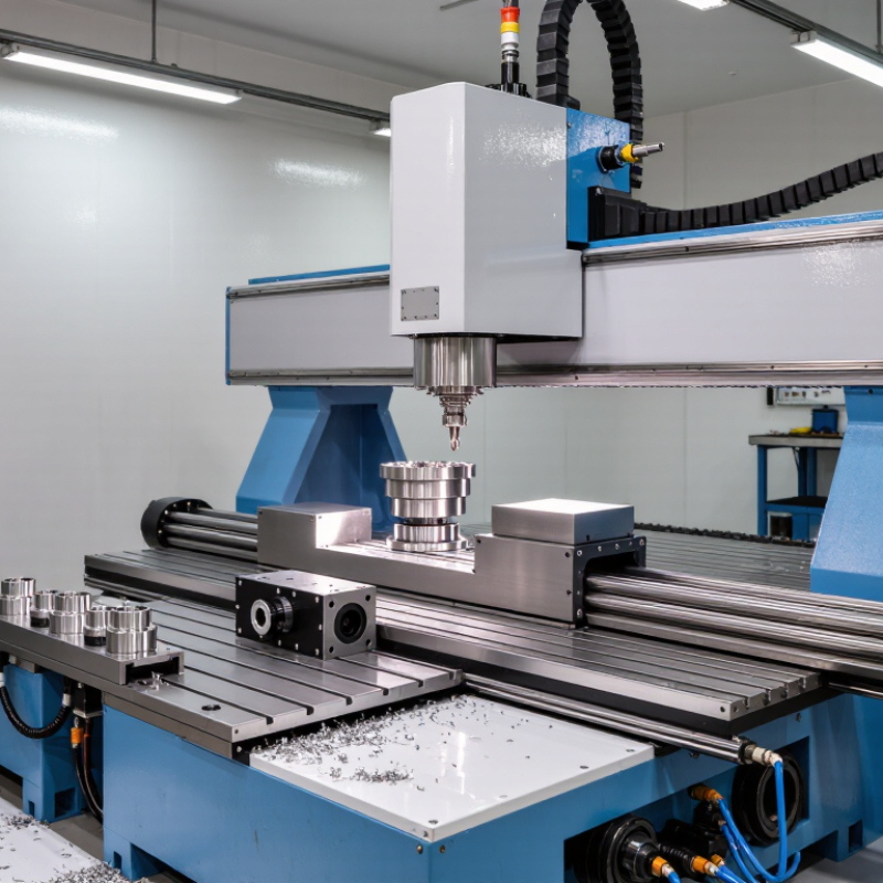
Cnc Machine Parts form the working anatomy of every computer numerical control system. They convert digital instructions into controlled cutting, drilling, turning, or milling movements. The spindle holds and rotates the tool. Bearings support smooth rotation. Guideways direct the machine table. Ball screws transfer motor power with measured precision. Servo motors provide movement, while the controller coordinates each axis. Small parts matter, too. A damaged seal can spread coolant. A worn bearing can leave visible lines on an aluminum surface.

CNC educator and author Mike Lynch has stated, “Accuracy begins with the machine’s mechanical condition.” This observation explains why operators inspect Cnc Machine Parts before blaming software or cutting data. A clean tool holder, correctly tensioned belt, and lubricated guideway can protect repeatability during long production runs. Yet the statement is not a complete rule. Temperature, material hardness, tool geometry, and operator judgment also influence results. That deserves attention.

This article examines what each major component does and where it fits inside the machine. It connects structure with practical use, from spindle assemblies to workholding devices and coolant systems. Readers will see why replacement parts must match the machine model, load, tolerance, and operating environment. A part may look interchangeable. It may not be.

Real workshops reveal the difference. Chips collect near covers. Vibration hides inside a loose coupling. Maintenance records often expose problems earlier than inspection alone. Understanding these details helps buyers, technicians, and machinists make safer, more reliable decisions. Mistakes still happen. Good knowledge reduces their cost.
What Are CNC Machine Parts and How Are They Used?

CNC Machine Architecture: Controllers, Frames, Spindles, and Drive Systems

What Are CNC Machine Parts and How Are They Used?

A CNC machine is an organized system of mechanical and electronic parts. The controller reads programmed coordinates and converts them into electrical commands. It manages motion, speed, tool changes, and emergency stops. Accuracy begins with the frame. A heavy, well-aligned frame resists vibration during cutting. Linear guides support smooth movement along each axis. Ball screws then transfer motor rotation into controlled table or spindle movement.

The spindle holds and rotates the cutting tool. Its bearings must remain stable under heat and cutting pressure. A powerful spindle is not always better. The correct speed depends on the material, tool diameter, and cutting depth. Drive systems include motors, couplings, screws, belts, and feedback devices. These parts determine acceleration, positioning accuracy, and surface finish. In practice, a small alignment error can leave visible lines on a metal surface.

Tips:

  • Check frame alignment before blaming the controller.
  • Listen for unusual spindle noise.
  • Keep guides clean and lubricated.
  • Measure backlash regularly.
  • Do not ignore heat buildup. It changes dimensions.

The controller and drive system must work as one unit. Feedback sensors report actual position, allowing corrections during movement. Without reliable feedback, commanded accuracy may remain only an assumption. I have found that maintenance records often reveal problems earlier than inspection alone. Still, no setup is perfect. Tool wear, temperature changes, and operator habits can affect results. A careful technician checks the machine under real cutting conditions, not only during an idle test.

3–5-Axis Motion: Servo Drives, Ball Screws, Guides, and Encoders

What Are CNC Machine Parts and How Are They Used?

3–5-Axis Motion: Servo Drives, Ball Screws, Guides, and Encoders

In a three-axis CNC machine, each linear axis converts programmed coordinates into controlled physical movement. A servo drive regulates motor torque, speed, and position through feedback. The ball screw then changes rotary motion into precise linear travel. Its preload reduces backlash, although excessive preload can create heat. Linear guides support the moving table or spindle carriage. They must resist cutting forces without binding. An encoder reports actual shaft or axis position. The controller compares that signal with the commanded position and corrects small errors. This closed loop matters during contouring, where tiny deviations affect the finished surface. The U.S. Department of Energy’s 2022 Motor Systems Market Assessment reports that motor-driven systems use about 70% of industrial electricity. Efficient tuning affects accuracy and operating cost. A cool cabinet is not enough.

Four- and five-axis machines add rotary axes around the workpiece or spindle. Their servo drives coordinate simultaneous motion, while encoders verify angular position. Ball screws still serve many linear axes. Rotary tables may use precision bearings or direct gearing. Guide selection depends on load, speed, contamination, and stiffness. ISO 230-2 testing separates positioning accuracy from repeatability, which is vital during acceptance checks. A machine can repeatedly return to one point yet miss the commanded coordinate. That is not always a software problem. Thermal growth, pitch error, loose preload, or encoder misalignment may be responsible. The 2024 World Robotics report highlights the growing role of connected maintenance, but data cannot repair poor assembly. Check backlash with a calibrated indicator, warm the machine, then measure again. The second result may challenge the first.

Cutting and Workholding Parts: Tools, Collets, Chucks, and Fixtures

CNC machine parts work together to remove material accurately and repeatedly. Cutting tools include end mills, drills, reamers, and inserts. Each tool suits a different operation, such as slotting, facing, or hole finishing. Tool holders connect the cutter to the spindle and control its position. Excessive tool stickout can cause vibration, poor surface finish, and premature edge wear. A shorter setup is usually more stable. Small details matter.

Workholding parts keep the workpiece fixed during cutting. Collets grip round shanks with even pressure and support precise, smaller-diameter tools. Chucks hold larger tools or workpieces, depending on the machine setup. Fixtures locate parts against dependable datums and prevent movement during repeated operations. Their design should allow chip clearance and safe access for the cutter. I have seen accurate programs produce poor parts because a fixture was slightly misaligned. That mistake is easy to overlook.

Tips: Check tool runout before critical cuts. Keep gripping surfaces clean. Tighten collets and chucks to the specified setting, not by guesswork. Use the shortest practical tool. Inspect the first part carefully, then question the setup if dimensions drift. A fixture may look rigid but still flex under load. Practical testing remains essential.

What Are CNC Machine Parts and How Are They Used?

Representative working-size ranges for common CNC cutting and workholding parts. Actual sizes vary by machine, standard, tooling system, and application.

Cutting tools remove material, while collets, chucks, and fixtures hold the tool or workpiece securely. The ranges shown are typical representative dimensions in millimeters: cutting tools generally use smaller diameters, collets provide precision tool gripping, chucks cover broader workpiece sizes, and fixtures are commonly designed around the overall workpiece envelope.

Coolant, Chip, and Safety Systems for Reliable CNC Machining

What Are CNC Machine Parts and How Are They Used?

Coolant, chip, and safety systems determine whether CNC parts perform reliably. Coolant removes heat from the cutting zone and reduces friction between the tool and workpiece. Operators should check concentration with a refractometer, not by appearance. Weak mixtures may encourage corrosion and microbial growth. Keep it visible. The U.S. National Institute for Occupational Safety and Health identifies skin and respiratory risks linked to metalworking-fluid exposure in its occupational criteria report. Poor maintenance makes those risks harder to control.

Chip systems protect accuracy as much as cleanliness. Conveyors, augers, and filtered chip tanks move hot fragments away from the tool. A blocked path can scratch finished surfaces or recut chips into the workpiece. In practice, small chips often reveal larger process problems. Excessive chip packing may indicate poor coolant flow, incorrect cutting parameters, or a dull tool. The fix is not always another accessory.

Safety systems include guards, door interlocks, emergency stops, and controlled access. OSHA estimates that effective machine guarding can prevent about 18,000 serious injuries and 800 deaths each year. The U.S. Bureau of Labor Statistics recorded 5,283 fatal occupational injuries in 2023, reinforcing the need for disciplined controls. Interlocks must be tested, not merely trusted. NIOSH guidance also supports ventilation where coolant mist may form. The weak point is usually human attention. Even experienced operators miss checks under production pressure.

What Are CNC Machine Parts and How Are They Used? - Coolant, Chip, and Safety Systems for Reliable CNC Machining

System or Part Primary Function How It Is Used Typical Materials or Specifications Reliability and Maintenance Considerations
Spindle Rotates the cutting tool or workholding device. Receives programmed speed commands and provides the cutting torque required for milling, drilling, or turning. Motor-driven assembly with precision bearings; common speed ranges are approximately 4,000–24,000 rpm depending on machine type. Check vibration, noise, temperature, runout, lubrication, and tool-holding condition. Excessive runout can reduce accuracy and tool life.
Linear Axes and Guideways Move the cutting tool or workpiece along programmed directions. Coordinate movement on the X, Y, and Z axes; additional rotary axes may orient the workpiece or tool. Hardened linear rails, recirculating ball guides, or box ways; positioning resolution may be measured in micrometers. Keep guideways clean, maintain lubrication, inspect for backlash, and avoid chip buildup that can cause positioning errors.
Ball Screws Convert motor rotation into accurate linear motion. Drive axis slides through a threaded screw and recirculating ball nut, supporting repeatable positioning. Precision-ground or rolled steel screw with hardened balls; preload is used to minimize backlash. Inspect for abnormal noise, heat, contamination, and lost motion. Use the specified lubricant and prevent coolant or chips from entering the nut.
Servo Motor and Drive Controls axis speed, position, and acceleration. Receives commands from the CNC controller and adjusts motor output using feedback from an encoder. AC servo motor, digital drive, and position feedback device; performance depends on tuning and load conditions. Monitor alarm codes, motor temperature, cable condition, and unexpected following errors. Keep electrical cabinets clean and adequately cooled.
Tool Holder and Collet Secures the cutting tool in the spindle. Transfers spindle rotation and cutting force while maintaining tool concentricity. Hardened alloy steel; common collet systems provide a defined clamping range and require clean contact surfaces. Clean taper and collet surfaces, inspect for wear, and tighten according to the tool-holder procedure. Damaged holders increase runout.
Workholding Device Holds and locates the workpiece during machining. Uses a vise, chuck, fixture, or clamping system to resist cutting forces and establish a repeatable datum. Steel, cast iron, aluminum, or modular fixture components; clamping force must match the workpiece and operation. Verify jaw contact, fixture alignment, clamping security, and clearance. Avoid distortion caused by excessive clamping force.
Coolant Tank and Pump Stores and circulates cutting fluid. Pumps coolant through nozzles toward the cutting zone to remove heat, lubricate contact areas, and flush chips. Water-miscible or straight cutting fluid; concentration commonly falls within the fluid supplier's specified range, often about 5%–10% for general machining. Measure concentration with a refractometer, remove tramp oil, clean the tank, and check pump flow. Incorrect concentration can cause corrosion, odor, or poor tool life.
Coolant Nozzles and Delivery Lines Direct coolant accurately at the cutting zone. Positioned manually or automatically to follow the tool and workpiece interface during cutting. Chemical-resistant tubing, adjustable nozzles, and sealed fittings; delivery pressure varies by machine and application. Remove blocked nozzles, inspect leaks, and confirm that flow reaches the actual cutting edge rather than only the chip area.
Chip Conveyor or Chip Auger Removes chips from the machining enclosure. Moves chips into a collection container, reducing recutting, coolant blockage, and operator exposure to sharp swarf. Steel belt, scraper, or screw conveyor; design depends on chip size, material, and coolant volume. Clear packed chips, inspect the drive and scraper, and never reach into a moving conveyor. Long stringy chips may require process or tooling changes.
Chip Guard and Enclosure Contains chips, coolant spray, and some machining noise. Surrounds the work area and provides a controlled space for automatic machining. Steel panels, transparent impact-resistant viewing windows, seals, and interlocked doors. Keep doors closed during operation, replace damaged windows, inspect seals, and do not bypass door interlocks.
CNC Controller Interprets the machining program and coordinates machine functions. Processes G-code, controls axes and spindle functions, and manages offsets, alarms, coolant, and auxiliary equipment. Industrial computer, motion-control hardware, display, program memory, and safety-related input signals. Verify program coordinates, tool offsets, feed rates, and work offsets. Back up programs and investigate alarms before restarting production.
Emergency Stop Circuit Stops hazardous machine motion in an emergency. Disconnects or removes motion power when an emergency-stop button is pressed. Red emergency-stop actuator, safety relay or controller, and monitored switching components. Test according to the machine's safety procedure. Emergency stop is not a substitute for isolation of electrical, pneumatic, hydraulic, or stored energy.
Tool Setter and Probe Measures tool length, tool diameter, or workpiece position. Automatically records offsets and can detect tool breakage or verify part dimensions between operations. Contact or non-contact sensor with calibrated reference surfaces and repeatable triggering. Keep contact surfaces clean, protect sensors from chips, and verify calibration after crashes or maintenance.
Lubrication System Delivers lubricant to moving mechanical components. Feeds metered lubricant to guideways, ball screws, or other specified points during scheduled cycles. Centralized oil or grease system with reservoir, pump, metering units, and distribution lines. Check reservoir level, line flow, alarms, and leaks. Under-lubrication accelerates wear, while excessive lubricant can attract chips.
Electrical Cabinet and Cooling Unit Protects and cools control electronics. Houses drives, relays, power supplies, and control components in a controlled environment. Enclosed electrical panel with filtered fan or air-conditioning unit; operating temperature must remain within specified limits. Keep doors closed, clean filters, inspect fans, and isolate electrical power before service. Moisture and conductive dust can cause failures.

The CNC Workflow: CAD/CAM, ISO 6983 G-Code, and Precision Control

What Are CNC Machine Parts and How Are They Used?

The CNC Workflow: CAD/CAM, ISO 6983 G-Code, and Precision Control

A CNC machine turns digital instructions into controlled cutting movements. Its spindle rotates the tool, while linear axes position the workpiece accurately. Servo drives move these axes, and encoders report their actual positions to the controller. A rigid table and reliable workholding prevent vibration during cutting. Coolant can reduce heat, clear chips, and protect the cutting edge. Small parts matter. A loose tool holder can create visible marks on an otherwise correct component.

The workflow usually begins with a CAD model containing the required dimensions and surfaces. CAM software converts that model into toolpaths for roughing, finishing, drilling, or threading. A postprocessor then creates ISO 6983 G-code for the specific controller. Operators check feed rates, spindle speed, tool offsets, and coordinate systems before machining. They may run the program above the workpiece first. This catches unsafe movements.

Precision control requires more than accurate code. Probing can locate a workpiece, while compensation adjusts tool length and diameter. Backlash, thermal growth, and worn inserts can still affect results. I have seen a tiny offset mistake leave a clean but undersized bore. That result looked professional at first. It was wrong. Measuring with calibrated gauges, documenting corrections, and reviewing the simulation provide stronger quality evidence. Even experienced machinists should question a perfect-looking program.