How to Choose the Right PSC Tool Holder?
Choosing the right Psc Tool Holder is not a minor purchasing decision. It directly affects tool stability, surface quality, changeover time, and machine performance. A holder may look suitable on a product page, yet fail when exposed to heavy milling or long production cycles.
In practical machining environments, the spindle interface must match exactly. Check the machine model, PSC size, gauge length, and allowable speed before comparing brands. Taper accuracy matters. So does contact quality. A reliable holder should provide strong radial and axial support, controlled runout, and secure clamping under load. For example, a high-speed finishing operation may require balanced construction, while rough milling may demand greater rigidity and impact resistance. These needs are different.
Coolant delivery also deserves attention. Internal channels can improve chip evacuation, but only when they align with the cutting tool and machine system. Material, coating, heat treatment, and manufacturing tolerance reveal more than appearance alone. Reputable suppliers should provide inspection data, technical drawings, and clear compatibility guidance. Independent verification is still wise. Specifications can be misunderstood.
There is no universal best holder. That is an uncomfortable truth. The correct choice depends on the machine, cutting conditions, workpiece material, and maintenance habits. Reviewing real machining results can expose weaknesses that catalog images hide. Measure runout, monitor tool life, and inspect the holder after repeated use. A careful selection process reduces costly surprises and supports safer, more consistent production.
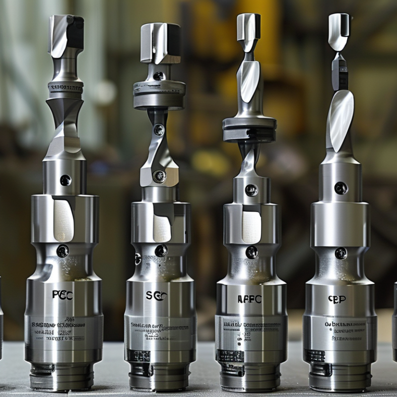
Define PSC by ISO 26623-1: Polygon geometry, taper, and dual contact
How to Choose the Right PSC Tool Holder?
ISO 26623-1 defines PSC through three practical features: polygon geometry, a tapered shank, and dual contact. The polygon transmits torque through multiple driving faces. The taper centers the holder inside the spindle. The flange then contacts the spindle face, creating axial support. This combined contact can reduce tool movement during heavy milling. It also makes cleanliness critical. A small chip on the flange can disturb seating.
Check the interface, not only the advertised size. Measure the spindle taper, flange condition, and available clamping stroke. A holder with poor face contact may show higher runout near the cutting edge. In production trials, I would record runout at 100 mm, cutting noise, and tool life. Five microns can matter. So can operator error. Coolant delivery, holder balance, and cutter projection also affect results. The holder alone cannot correct excessive overhang.
Industry forecasts show why this choice receives attention. Fortune Business Insights estimated the global machine tool market at about 86 billion US dollars in 2023, with continued growth toward 2032. The 2024 Gardner Business Media World Machine Tool Survey also reported strong demand for automated, high-performance machining equipment. These reports measure machine tools, not PSC holders directly. Their estimates therefore need careful interpretation. Still, tighter spindle performance increases the value of stable interfaces. Select PSC dimensions directly from ISO 26623-1 and verify them against the machine builder’s data. Guessing is expensive.
Match PSC size to spindle speed, from 10,000 to 30,000 rpm
Choosing a PSC tool holder starts with spindle speed, not the catalog photograph. At 10,000 rpm, a larger PSC size can provide useful rigidity for deep cuts and heavy roughing. Its wider contact area helps resist bending. However, weight increases. That matters during acceleration, braking, and spindle bearing operation.
Around 20,000 rpm, review the holder’s rated speed, balance quality, gripping length, and tool projection. A medium PSC size often suits stable milling with moderate cutting loads. At 30,000 rpm, smaller and lighter holders may reduce centrifugal force and vibration. They work best with short tools, precise collets, and carefully balanced assemblies. Speed alone does not decide compatibility.
I once treated the PSC size as the main answer. It was a mistake. The machine’s spindle limit, coolant method, cutting diameter, and actual tool weight changed the result. Check the holder rating under the complete assembly, not the empty holder. Measure runout near the tool tip. Even a few microns can mark a finished surface at high speed. A practical test should begin at a lower rpm, then increase gradually while monitoring noise, vibration, and temperature. Some assumptions fail here. The manufacturer’s technical data and ISO 26623 requirements should remain the final reference.
How to Choose the Right PSC Tool Holder? - Match PSC Size to Spindle Speed, from 10,000 to 30,000 rpm
| Target Spindle Speed | Preferred PSC Size Range | Typical Machining Focus | Why This Selection Works | Selection Checks |
| 10,000 rpm | PSC 50–PSC 80 | General milling, roughing, drilling, and medium-to-large tools | Lower rotational speed generally permits a larger and more rigid toolholder, which is useful for higher cutting forces. | Confirm toolholder overhang, pull-in force, tool weight, and the spindle’s published PSC interface rating. |
| 15,000 rpm | PSC 40–PSC 63 | General-purpose milling and mixed roughing/finishing work | A medium PSC size provides a practical balance between radial stiffness, tool access, and rotating mass. | Use a holder specifically rated for the intended speed and check that the complete assembly is correctly balanced. |
| 20,000 rpm | PSC 32–PSC 50 | High-speed finishing, aluminum machining, and smaller-diameter cutters | Smaller interfaces and compact holders can reduce rotating mass and improve access, provided rigidity remains sufficient. | Check dynamic balance, gripping method, permissible tool projection, and the effect of coolant delivery on balance. |
| 25,000 rpm | PSC 32–PSC 40 | High-speed finishing, die and mold work, and small cutting tools | A compact, accurately balanced holder helps control centrifugal forces and vibration at higher rotational speeds. | Verify the holder’s certified maximum speed, balance condition, runout specification, and spindle-to-holder cleanliness. |
| 30,000 rpm | PSC 32; PSC 40 only when specifically rated | Very high-speed finishing with small-diameter tools and short projections | The smallest suitable PSC interface minimizes rotating mass, but stiffness and speed certification become critical. | Do not select by PSC size alone; confirm the complete holder-and-tool assembly rating, balancing requirements, tool length, and machine safety limits. |
Important engineering note: PSC 32, PSC 40, PSC 50, PSC 63, and PSC 80 are nominal interface sizes within the polygonal-shank tooling system. PSC size alone does not define a universal maximum spindle speed. The allowable speed depends on the specific toolholder design, balancing condition, tool type, projection length, retention method, spindle rating, and machine manufacturer’s safety limits. Always use the lowest applicable rated speed.
Quick rule: Choose the largest PSC size that provides the required rigidity and tool access at lower speeds; move toward a smaller PSC size at higher speeds only when the complete assembly is explicitly rated, dynamically balanced, and sufficiently rigid for the cutting load.
Set precision targets: ≤3 μm runout at 4×D and balance grade G2.5
How to Choose the Right PSC Tool Holder?
Set measurable targets before comparing PSC tool holders. For demanding milling, specify no more than 3 μm radial runout at 4×D. Here, D means the cutting tool diameter. This target matters because a small error grows at the tool tip. A 10 mm cutter checked at 40 mm needs careful control. Ask how the supplier measures runout, including gauge length, probing force, and temperature.
Balance grade G2.5 should match the spindle’s operating speed, not only its maximum rating. A holder may meet G2.5 at one speed but behave differently at another. Request the test speed and residual unbalance value. Check the tool, holder, pull stud, coolant delivery, and retention system as one assembly. Precision is rarely created by one component alone.
In daily use, clean every mating surface. One tiny chip can exceed the runout limit. I once blamed the holder for poor surface finish, then found dust beneath the flange. That mistake was avoidable. Use a calibrated gauge, record readings at several rotations, and inspect wear after repeated changes. The 3 μm target is useful, but it is not permanent. Rechecking exposes the uncomfortable gaps between laboratory results and real machining.
Choose clamping technology for cutting loads: hydraulic, shrink-fit, or milling
How to Choose the Right PSC Tool Holder?
Choosing the right PSC tool holder starts with cutting load, not catalog appearance. A hydraulic holder suits finishing and moderate roughing. Its oil chamber applies even radial pressure around the tool. This helps reduce runout and protects delicate carbide shanks. Shrink-fit holders provide a slim nose and strong concentric clamping. They work well in deep pockets and high-speed machining. However, heating and cooling require controlled equipment and disciplined handling. Milling holders use mechanical contact and transmit high torque during interrupted cuts. They are practical for heavy roughing, large cutters, and unstable setups. The trade-off is a larger nose and possible interference in tight features.
Tips: Match holder stiffness to the actual cutting load. Check gauge length before choosing a slim design. Keep tool projection short. Measure runout at the cutting edge, not only at the holder. Follow the recommended torque and heating limits. Clean the PSC interface and tool shank carefully. One small chip can alter alignment. Test with a short cutting pass.
In shop trials, I have seen a precise holder perform poorly with excessive projection. The holder was not the real problem. The setup was. Hydraulic clamping can also disappoint when the shank is dirty or undersized. Shrink-fit feels rigid, yet poor thermal control may damage the holder or tool. Milling clamping is powerful, but balance and accessibility still matter. Review vibration marks, spindle load, and edge wear after each trial. Selection should follow evidence from the machine, material, cutter diameter, and operation. Sometimes the best choice is less elegant than expected.
How to Choose the Right PSC Tool Holder?
Choose clamping technology according to cutting loads, required runout, damping, and machining speed.
The chart shows a representative suitability score from 1 to 5 for common cutting conditions. Hydraulic holders provide strong damping and reliable performance for finishing and moderate loads. Shrink-fit holders are well suited to high-speed machining and low runout. Milling chucks generally provide the strongest torque transmission for heavy milling, although their runout and balance can be less favorable than shrink-fit or hydraulic systems. Actual performance depends on holder size, tool diameter, projection length, cutting parameters, and proper maintenance.
Verify ATC compatibility and through-tool coolant capacity up to 20 bar
How to Choose the Right PSC Tool Holder?
Choosing a PSC tool holder starts with the automatic tool changer, not the cutting tool. Check the spindle interface, gripper position, flange clearance, and tool-change orientation. A holder may fit the spindle but still collide with the ATC arm. Measure the complete assembly at the machine.
Through-tool coolant requires closer verification. Confirm that the holder is rated for coolant pressure up to 20 bar. Then check the cutting tool, sealing interface, and machine supply separately. The holder cannot safely compensate for a weak connection or blocked passage. Inspect the coolant outlet for burrs, contamination, and poor alignment. Small restrictions can reduce flow before coolant reaches the cutting edge.
Run a controlled test before full production. Use the intended coolant, pressure, tool length, and spindle speed. Look for leakage around the retention area and unusual vibration during tool changes. A pressure rating on a catalog page is useful, but it does not prove stable performance in every setup. This is where selection can become imperfect. Operators sometimes verify pressure but overlook flow rate, filtration, or chip evacuation. Record the actual result at the machine. That evidence is more reliable than an assumption. Evaluate tool balance and runout as well, especially with long extensions or high-speed machining. A few minutes of checking can prevent repeated ATC faults, coolant loss, and inconsistent tool life.