How to Choose the Right MPO Patch Cable?
Choosing the right MPO Patch cable can simplify high-density fiber installations, but the connector alone does not determine compatibility. Fiber type, core count, polarity, and end-face configuration all matter. A cable that looks correct may still fail to connect the intended transmit and receive paths. Small details count.
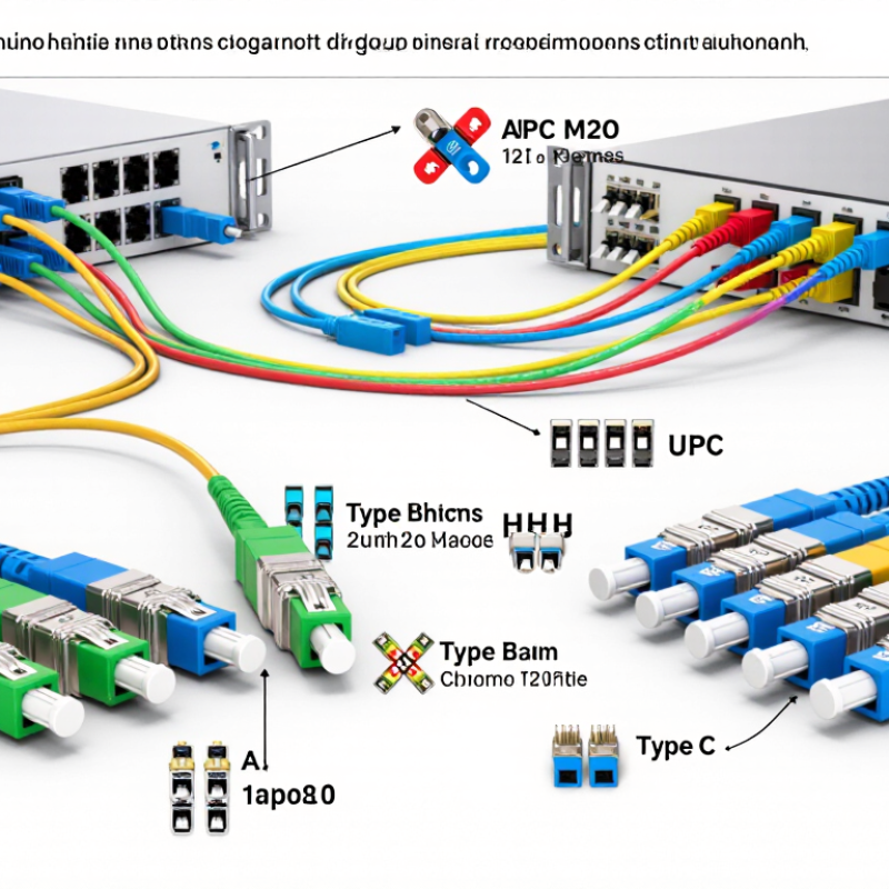
Start with the equipment at both ends. Confirm whether the system uses single-mode or multimode fiber, and check the required fiber count, such as 8, 12, or 24 fibers. Match the connector gender and key orientation to the adapters or cassettes. Also verify the polarity method specified for your link. Type A, Type B, and Type C arrangements route fibers differently, so choosing by appearance alone is risky.
Performance deserves a close look. Review the supplier’s insertion-loss specifications and test documentation, especially for links with several mated connections. Confirm that the MPO end-face type is compatible with the connected hardware; APC and UPC interfaces should not be treated as interchangeable. Check cable length and routing needs, too. Tight bends behind a rack can strain fibers and complicate maintenance.
There is no single best cable for every network. That is easy to overlook when comparing products quickly. A careful selection starts with the equipment documentation and the link design, then checks each cable specification against both. This guide explains those choices in practical terms, helping you compare options without relying on connector names alone. Verify uncertain details with the equipment or cable manufacturer before ordering.
Identify the Network Requirements and Intended Application
Before selecting an MPO patch cable, define what the link must carry and where it will run. A short connection inside a rack may have different needs from a trunk spanning several rooms. Check the equipment interfaces, supported fiber type, required fiber count, and target data rate. Single-mode and multimode systems are not interchangeable. Neither are all MPO connector configurations.
Map the complete path, including any cassette or breakout assembly. Confirm connector gender and pin arrangement at both ends, then verify polarity against the transceivers’ transmit and receive positions. Small details matter. A cable can fit physically and still fail to establish the intended link. Estimate the link length and check the optical loss budget, especially where several connections add insertion loss. Keep room for planned capacity, but avoid paying for fiber counts or performance the application cannot use. It is easy to overlook the rack layout during planning; measure the actual route, including bends and service loops. I would also record the selected polarity and test results, since relying on memory is a weak process. Before installation, inspect and clean the end faces, then confirm continuity and polarity with suitable test equipment.
Select the Fiber Type, Fiber Count, and Cable Length
MPO patch cable selection starts with fiber type. Match it to the optical modules and installed fiber plant, not just the port label. Single-mode fiber suits longer links and single-mode optics; multimode fiber serves shorter data-center runs with compatible optics. OM3, OM4, and OM5 should not be treated as interchangeable. Check equipment specifications and the link budget. A mismatch can leave a link dark. Color can mislead; it is only a clue.
Choose the fiber count to fit the MPO interface and channel plan. Common trunks carry 8, 12, or 24 fibers, while some arrangements use 16. Confirm the connector format, polarity, and how many fibers the transceivers use. More fibers are not automatically better if unused strands complicate testing. Measure the installed route, including rack turns and service loops, before ordering. Measure twice. A cable pulled tight can strain connectors, while excess slack may block airflow or snag during maintenance. Leave usable slack and respect the cable’s minimum bend radius. I would recheck the route at the rack; one missed turn can change the required length.
Choose the MPO Connector, Gender, and Polarity
Choose an MPO connector that matches the equipment ports at both ends. Check the fiber count, such as 12 or 16 fibers, and confirm whether the interface requires a flat UPC or angled APC finish. These ends are not interchangeable. Connector key orientation matters, too; a cable can fit physically yet fail to align with the intended optical path.
Check gender before ordering. A male MPO connector has guide pins, while a female connector has empty alignment holes. The connected ports or adapters must accept the cable’s ends. I still double-check this detail against equipment drawings; connector photos can hide the pins. It is easy to miss.
Then verify polarity for the complete link, not just the patch cable. Polarity describes how transmit and receive fibers map from one end to the other. Type A keeps positions straight, Type B reverses them, and Type C swaps fiber pairs. The required method depends on the transceivers, trunk cables, and cassette arrangement. For example, a link may light at one end but fail to pass traffic if transmit fibers meet transmit fibers. Check the cable label and port map, then confirm the path from end to end. A small test before installing a full rack can catch an assumption that looked obvious on paper.
How to Choose the Right MPO Patch Cable
Choose a fiber count that matches the equipment and link design. Common MPO formats include 8, 12, 16, 24, and 32 fibers; the connector and cable must use compatible configurations. Check gender: a pinned (male) connector mates with an unpinned (female) connector. Then select polarity—Type A, B, or C—to ensure transmit and receive paths map correctly across the link.
Match the Cable to the System’s Performance Requirements
Match the MPO patch cable to the optical transceivers, not just the rack layout. The Ethernet Alliance’s 2024 Ethernet Roadmap tracks 400G and 800G deployments, where lane count, fiber type, and connector mapping affect compatibility. IEEE 802.3bs defines 400 Gb/s Ethernet; some parallel-optics designs use multiple transmit and receive fibers. Check the transceiver datasheet before ordering. An MPO-12 cable may fit the panel but still fail the link’s fiber-count or polarity requirements.
Distance and loss matter just as much. Multimode OM4 can suit short data-center links, while single-mode OS2 is commonly selected for longer reaches. Confirm the supported wavelength and reach in the optical module specifications. Then compare connector loss against the channel budget, including adapters and splices. TIA-568.3-E provides optical-fiber cabling requirements; use it alongside the equipment documentation, not as a substitute for it. Keep polarity consistent end to end. Small mismatch, real downtime. I have seen cable schedules omit keying orientation; the drawing looked tidy, but the installed link needed rework. Before deployment, verify fiber count, polarity method, insertion loss, and cleaning condition on the actual assembly. A quick visual check helps, but it cannot prove performance.