
Made in America

Get Connected With

JointsCouplings.com White Logo

Opening Hours M-F: 07:00 AM to 4:00 PM (PST)

What Are Bevel Gears Types Uses and Applications?

Bevel Gears are essential when machinery must transfer torque between intersecting shafts, often at a 90-degree angle. Their conical teeth redirect motion while controlling speed, load, noise, and installation space. Straight bevel gears suit moderate-speed systems and simpler manufacturing. Spiral bevel gears offer smoother engagement, quieter operation, and stronger load distribution. Zerol bevel gears provide a practical compromise between both designs. Hypoid gears extend this concept with offset shafts and higher reduction ratios.

Their importance is visible across automotive drivetrains, industrial robots, mining conveyors, marine propulsion, agricultural equipment, and wind turbines. Grand View Research’s 2024 Gears Market analysis identifies transportation, industrial automation, and renewable energy as major demand areas. MarketsandMarkets also projects approximately 6% annual growth for the broader gears market in the coming years. These figures are useful indicators, not guarantees. Market definitions differ, and bevel-specific data remains less consistent.

Selecting the correct design requires more than matching a ratio. Engineers must examine torque, shaft angle, tooth geometry, lubrication, mounting accuracy, backlash, and operating temperature. AGMA standards and ISO 23509 provide recognized guidance for bevel gear geometry and rating practices. A gear may appear oversized yet fail under poor alignment. Small details matter. Tooth contact patterns, housing stiffness, and surface hardness can decide service life. This guide explains the main Bevel Gears types, their practical uses, and the engineering choices behind reliable applications. It also acknowledges an uncomfortable point: no universal gear design performs perfectly in every machine.
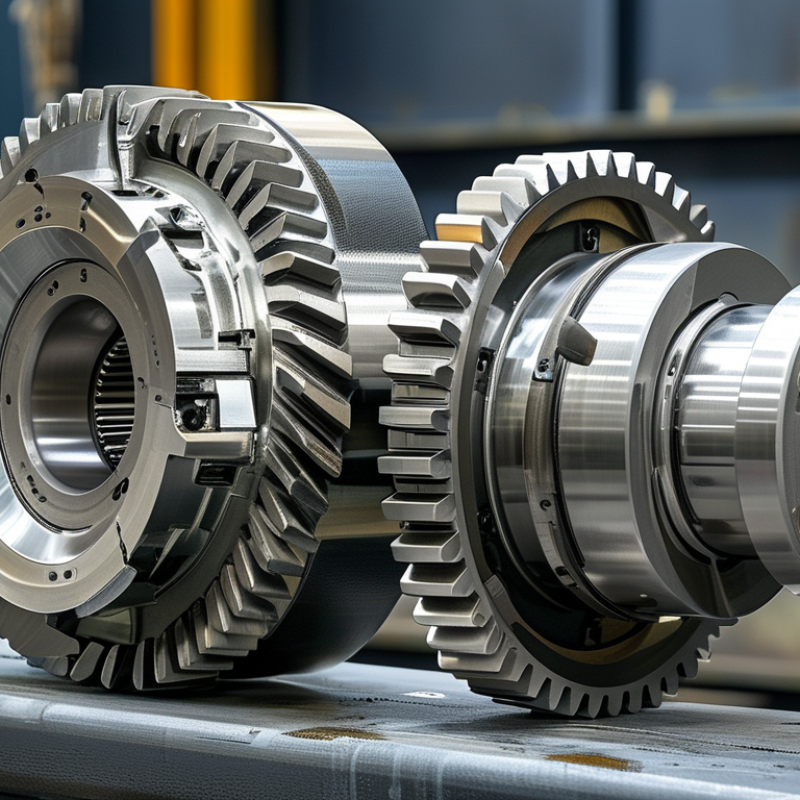
What Are Bevel Gears Types Uses and Applications?

What Is a Bevel Gear and How Does It Work?

A bevel gear changes torque direction, usually through 90 degrees, while transferring motion between intersecting shafts. Its teeth are cut on a conical surface, not a flat cylinder. As the driving gear turns, each tooth pushes across the mating gear’s angled face. This creates a compact right-angle drive for differentials, pumps, conveyors, and machine tools. The principle is simple. The alignment is not.

Straight bevel gears are economical and suit moderate speeds. Spiral bevel gears use curved teeth, producing smoother engagement and lower noise. Zerol bevel gears sit between these designs. Hypoid gears offset the shafts and provide higher contact ratios, although sliding friction increases. According to ISO 23509:2016, accurate bevel-gear geometry requires controlled pitch angles, tooth proportions, and reference systems. Small errors can produce edge contact, heat, and early wear.

Energy use makes design discipline important. The U.S. Department of Energy reports that motor-driven systems may consume 60–70% of industrial electricity. A poorly adjusted bevel gearbox can waste part of that input through friction, vibration, and lubrication losses. Industry rating guidance from the American Gear Manufacturers Association also stresses load, speed, material, and service-factor calculations. In practice, I would inspect contact patterns after assembly, not trust calculations alone. That lesson is easy to miss. Temperature, backlash, and mounting stiffness often reveal problems before failure.

How Are Bevel Gears Classified by Design and Tooth Shape?

Bevel gears are classified mainly by their design, shaft arrangement, and tooth shape. Their teeth sit on a cone-shaped surface, allowing power to turn through an angle.

Straight bevel gears have radial teeth that meet suddenly. They are simple, economical, and suitable for moderate speeds. However, they can produce noticeable noise and vibration.

Spiral bevel gears use curved teeth that engage gradually. This creates smoother motion, higher contact ratios, and better load capacity.

Zerol bevel gears have curved teeth with nearly zero spiral angle. They offer a compromise between straight and spiral designs. Hypoid gears resemble spiral bevel gears, but their shafts are offset rather than intersecting. This design supports compact layouts and high torque transmission. The classification is not perfectly tidy. Some manufacturers use different terms for similar tooth geometries.

Tips: Check shaft alignment before selecting a gear. Intersecting shafts suit standard bevel designs. Offset shafts may require hypoid gearing. Consider speed, torque, noise, lubrication, and available space. A gear that looks suitable may still fail under shock loads. Practical testing remains valuable, especially when loads change during operation.

What Are the Main Types of Bevel Gears?

Bevel gears transmit motion between intersecting shafts, often at a 90-degree angle. Their tooth shape strongly affects noise, load capacity, efficiency, and maintenance needs. Straight bevel gears have flat, radial teeth. They are simple to manufacture and suitable for moderate speeds, such as hand tools, small conveyors, and basic right-angle drives. However, their teeth engage suddenly. That impact can create noticeable noise and vibration.

Spiral bevel gears use curved teeth that engage gradually. This design supports higher speeds, smoother operation, and greater torque. They appear in vehicle differentials, industrial reducers, and precision machinery. Zerol bevel gears resemble spiral gears, but their tooth curvature is nearly zero at the center. They offer quieter operation than straight gears while retaining simpler shaft-thrust behavior. Hypoid gears place the shafts on offset centerlines. This allows lower vehicle floors and compact drive layouts, but sliding contact increases heat and demands careful lubrication.

Miter gears are matched bevel gears with equal tooth counts and a one-to-one speed ratio. They change shaft direction without changing rotational speed. Choosing among these types requires checking speed, torque, shaft angle, space, lubrication, and expected noise. A common mistake is selecting by torque alone. That shortcut can fail. Tooth contact, housing stiffness, and alignment may matter more in real service. Small mounting errors can leave polished marks on only one side of a tooth. Dawdling? No—inspect the contact pattern before approving the design.

What Are Bevel Gears Types Uses and Applications? - What Are the Main Types of Bevel Gears?

Bevel Gear Type Tooth Geometry Typical Shaft Arrangement Main Characteristics Common Advantages Typical Applications
Straight Bevel Gear Radial, straight teeth arranged on a conical pitch surface. Usually intersects at 90°, although other angles are possible. Simple tooth form with direct engagement and relatively uncomplicated manufacturing. Simple design Cost-effective Suitable for moderate speeds and loads when noise requirements are limited. Manual mechanisms, low-speed drives, right-angle transmissions, agricultural equipment, and general industrial machinery.
Spiral Bevel Gear Curved teeth arranged along the conical pitch surface. Intersecting shafts, commonly at 90°. Gradual tooth engagement provides smoother contact than straight bevel gears. Smooth operation Higher load capacity Better suited to higher speeds and reduced vibration. Vehicle differentials, industrial gearboxes, machine tools, marine drives, and high-performance power transmission systems.
Zerol Bevel Gear Curved teeth with a tooth trace that is approximately transverse to the gear face, producing little or no apparent spiral angle. Intersecting shafts, commonly at 90°. Combines some operating characteristics of straight and spiral bevel gears. Reduced end thrust Quieter than straight teeth Provides a useful option where spiral gearing is not preferred. Compact right-angle drives, precision machinery, industrial reducers, and applications requiring controlled axial forces.
Hypoid Gear Spiral bevel-style teeth with non-intersecting, offset axes. Usually crossed shafts with an intentional offset, often near 90°. Allows the pinion axis to be positioned below or above the gear axis. High torque capability Compact packaging Can provide quiet operation and a lower drive-line position. Automotive final drives, rear axles, compact powertrains, and offset right-angle transmission systems.
Miter Gear Usually straight or spiral bevel teeth with equal tooth counts. Intersecting shafts, typically at 90°. Transfers motion through a right angle without changing speed ratio when the mating gears have equal numbers of teeth. 1:1 speed ratio Direction change Useful when only the direction of rotation must be changed. Conveyors, hand-operated mechanisms, indexing equipment, packaging machinery, and right-angle motion-transfer systems.
Crown Gear Teeth project approximately perpendicular to the gear face, creating a crown-like profile. Usually meshes with a pinion on intersecting or specially arranged shafts. Can transmit motion between shafts at a right angle without the conical form used by conventional bevel gears. Specialized geometry Flexible meshing options Useful in selected low-speed or motion-control mechanisms. Clocks, mechanical instruments, educational mechanisms, specialized indexing devices, and low-speed motion systems.
Face Gear Teeth are formed on the planar face of a gear rather than primarily on a conical surface. Often used with a cylindrical pinion whose axis is arranged approximately perpendicular to the face gear. Provides a compact right-angle transmission arrangement with a distinctive tooth layout. Compact layout Design flexibility Can be useful where conventional bevel gear geometry is difficult to package. Robotics, aerospace mechanisms, compact actuators, precision instruments, and specialized industrial drives.

Note: Actual performance depends on tooth geometry, module or diametral pitch, material, heat treatment, lubrication, alignment, speed, load, and manufacturing accuracy.

How Do Bevel Gears Transfer Motion Between Shafts?

Bevel gears transfer rotary motion between shafts whose axes meet, commonly at ninety degrees. Each gear has teeth cut on a truncated cone. When the driving gear turns, its teeth push the mating gear across the cone surface. This changes both the shaft direction and the available torque. The result is direct. Gear ratio depends on tooth count: a smaller driving gear can increase torque while reducing output speed. Reversing the tooth arrangement changes the direction of power flow, but not the basic transfer principle.

Straight bevel gears suit moderate speeds and simpler machinery. Spiral bevel gears use angled teeth, creating smoother engagement and lower operating noise. Their tooth contact develops gradually. Miter gears use equal tooth counts, so they redirect motion without changing speed. Hypoid designs allow offset shafts and can carry heavy loads, although their sliding contact demands careful lubrication.

In practical installations, alignment matters as much as gear geometry. Even a small mounting error can create uneven tooth contact, heat, and premature wear. Technicians often inspect the contact pattern with marking compound, then adjust shims or housing position. Backlash must remain within the equipment designer’s specified range. Too little backlash may cause binding when components expand. Too much can produce impact noise and vibration. Lubricant selection also depends on load, speed, and tooth material. Calculations help, but they can mislead when real assembly tolerances are ignored. A quiet test run is useful, yet it does not replace checking temperature and tooth contact after operating under load.

Bevel Gear Types, Uses, and Motion Transfer

Bevel gears transmit rotary motion between intersecting shafts by using conical tooth surfaces. In a common right-angle arrangement, the shafts intersect at approximately 90 degrees. The output speed and torque depend on the ratio between the driven gear and the driving gear.

For example, a 2:1 ratio means the driven bevel gear turns once for every two revolutions of the driving gear, while the available output torque increases approximately in proportion to the ratio before efficiency losses. Straight bevel gears are simple and economical, spiral bevel gears provide smoother and quieter operation, zerol bevel gears use curved teeth with near-zero spiral angle, and hypoid gears use offset shafts to achieve compact, high-ratio drives.

Where Are Bevel Gears Used in Industry and Machinery?

Bevel gears are used where power must turn through an angle, usually 90 degrees. Their conical tooth surfaces transfer rotation between intersecting shafts. This makes them valuable in compact industrial machinery. Straight bevel gears suit moderate speeds and simpler equipment. Spiral bevel gears provide smoother contact and lower noise at higher speeds. The choice depends on load, speed, space, and maintenance access. Small details matter.

In manufacturing plants, bevel gears appear in machine tools, conveyor drives, mixers, pumps, and automated positioning systems. A right-angle gearbox can fit beneath a conveyor, leaving the working area clear. In packaging machinery, bevel gears redirect motion between vertical and horizontal shafts.

Mining equipment uses stronger gear sets for crushers and material-handling systems. Agricultural machines also use them in drivetrains and cutting mechanisms. Vehicle differentials use bevel gearing to divide torque while allowing wheels to rotate at different speeds. These applications demand accurate alignment and controlled backlash.

Reliable performance begins with practical inspection. Engineers check tooth contact, shaft deflection, lubrication, housing stiffness, and operating temperature. A gear may appear correctly sized but still fail under shock loads or poor alignment. The first design is often wrong. Testing under realistic speed and load can reveal vibration that calculations miss. Maintenance teams should look for pitting, unusual noise, metallic particles, and rising temperature. In dusty areas, seals and filtration deserve careful attention. In wet environments, corrosion protection becomes equally important. Good selection is not only about torque capacity; it also considers installation errors, service intervals, and the cost of unexpected downtime.